
Why Conventional Suspensions Fail in Planetary Robotics
Standard spring-and-damper automotive suspensions fail when navigating boulders, steep rock faces, and soft sand. Springs store kinetic energy that causes chassis bounce, instability, and wheel slippage.
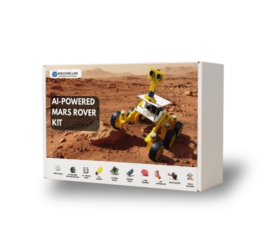
To overcome this, NASA planetary rovers (Curiosity, Perseverance) and the RoboZoneX AI-Powered Mars Rover Kit use the Rocker-Bogie mechanical linkage system—a passive kinematic mechanism that distributes equal ground pressure across all six wheels without a single spring.
Mechanical Linkage Geometry Explained
The Rocker-Bogie mechanism consists of three primary mechanical components:
- The Rocker (Larger Main Link): Pivots at the central chassis differential axle and extends to the front wheel and rear bogie joint.
- The Bogie (Smaller Rear Link): Pivots at the end of the rocker and connects the middle and rear wheels.
- The Differential Crossbar: Couples the left and right rockers across the top chassis. When one side lifts over a 20cm obstacle, the differential forces the opposite side downward, keeping all 6 wheels in contact with the ground.
       [ Differential Crossbar ]
           /               \
     [ Left Rocker ]   [ Right Rocker ]
       /        \         /        \
  (Wheel 1)   [ Bogie ] (Wheel 4)  [ Bogie ]
              /     \             /     \
         (Wheel 2)(Wheel 3)  (Wheel 5)(Wheel 6)
Obstacle Climb Ratio
The geometry allows the rover to climb obstacles up to 2x the wheel diameter while maintaining chassis pitch angles below 15°.
Multi-Motor Drive Architecture & Power Distribution
The Mars Rover Kit utilizes six high-torque metal gear motors driven by dual L298N or TB6612FNG H-bridge drivers controlled via ESP32 PWM signals:
// ESP32 Motor Pin Assignments (Left & Right Banks)
const int PWM_LEFT = 18;
const int DIR_LEFT_1 = 19;
const int DIR_LEFT_2 = 21;

const int PWM_RIGHT = 22;
const int DIR_RIGHT_1 = 23;
const int DIR_RIGHT_2 = 25;

void configureMotorPWM() {
  ledcAttach(PWM_LEFT, 20000, 8);   // 20kHz frequency, 8-bit resolution
  ledcAttach(PWM_RIGHT, 20000, 8);
}

void setRoverVelocity(int leftSpeed, int rightSpeed) {
  // Speed bounds: -255 to +255
  digitalWrite(DIR_LEFT_1, leftSpeed >= 0 ? HIGH : LOW);
  digitalWrite(DIR_LEFT_2, leftSpeed >= 0 ? LOW : HIGH);
  ledcWrite(PWM_LEFT, abs(leftSpeed));

  digitalWrite(DIR_RIGHT_1, rightSpeed >= 0 ? HIGH : LOW);
  digitalWrite(DIR_RIGHT_2, rightSpeed >= 0 ? LOW : HIGH);
  ledcWrite(PWM_RIGHT, abs(rightSpeed));
}
Sensor Fusion & Real-Time ESP32 Telemetry
An autonomous rover must monitor its attitude in real time to prevent rollovers. We integrate an MPU-6050 6-Axis Gyroscope/Accelerometer over I2C to calculate real-time roll, pitch, and yaw angles:
#include <Wire.h>
#include <MPU6050_light.h>

MPU6050 mpu(Wire);

void setupIMU() {
  Wire.begin(21, 22); // ESP32 SDA=21, SCL=22
  mpu.begin();
  mpu.calcOffsets();  // Keep rover stationary during auto-calibration
}

void monitorInclineSafety() {
  mpu.update();
  float pitch = mpu.getAngleX();
  float roll = mpu.getAngleY();

  // Automatic rollover prevention override
  if (abs(pitch) > 35.0 || abs(roll) > 35.0) {
    setRoverVelocity(0, 0); // Emergency stop
    Serial.println("[SAFETY HALT]: Hazardous Incline Angle Detected!");
  }
}
Summary & Classroom Outcomes
Building the Mars Rover kit provides students with practical exposure across:
- Mechanical Linkage Analysis & CAD Prototyping
- H-Bridge PWM Motor Speed Profiling
- I2C Sensor Fusion (IMU + Ultrasonic + Edge Cameras)
- WebSockets / Wi-Fi Autonomous Telemetry
This combination shifts STEM education from theoretical textbook formulas into active, field-tested engineering development.