Robozonex
Loading page content...
Loading page content...
Discover in-depth robotics tutorials, hardware build logs, system architecture updates, and industry insights from our team.
The Hidden Bottleneck in STEM Education: Breadboard Fatigue Ask any robotics instructor what consumes 80% of lab time, and the answer is rarely code—it is loose jumper wires, faulty breadboard spring clips, and parasitic voltage drops. When students work on IoT and Edge AI projects involving Wi-Fi bursts (ESP32 peaks up to 500mA) and servo motor inductive kickback, breadboards introduce high ground bounce and unpredictable brownout resets. At RoboZoneX Labs, we solve this by designing and manufacturing custom Smart Embedded Training Boards in-house. In this article, we share our design methodology from schematic capture to Gerber manufacturing. --- 1. Power Architecture & Voltage Isolation Robotics boards deal with two distinct power domains: 1. Noisy Inductive Rail (5V-9V / 2A-5A): High-current servos, DC motors, solenoid valves. 2. Clean Digital Logic Rail (3.3V / 1A): Microcontrollers (ESP32 / STM32), precision sensors (IMUs, environmental sensors). mermaid flowchart TD A"DC Barrel Jack (7.4V - 12V)" --> B"Schottky Diode (Reverse Polarity Protection)" B --> C"Buck Regulator (5V 3A)" B --> D"LDO Regulator (3.3V 1A Clean)" C --> E"Servos & Motors" D --...
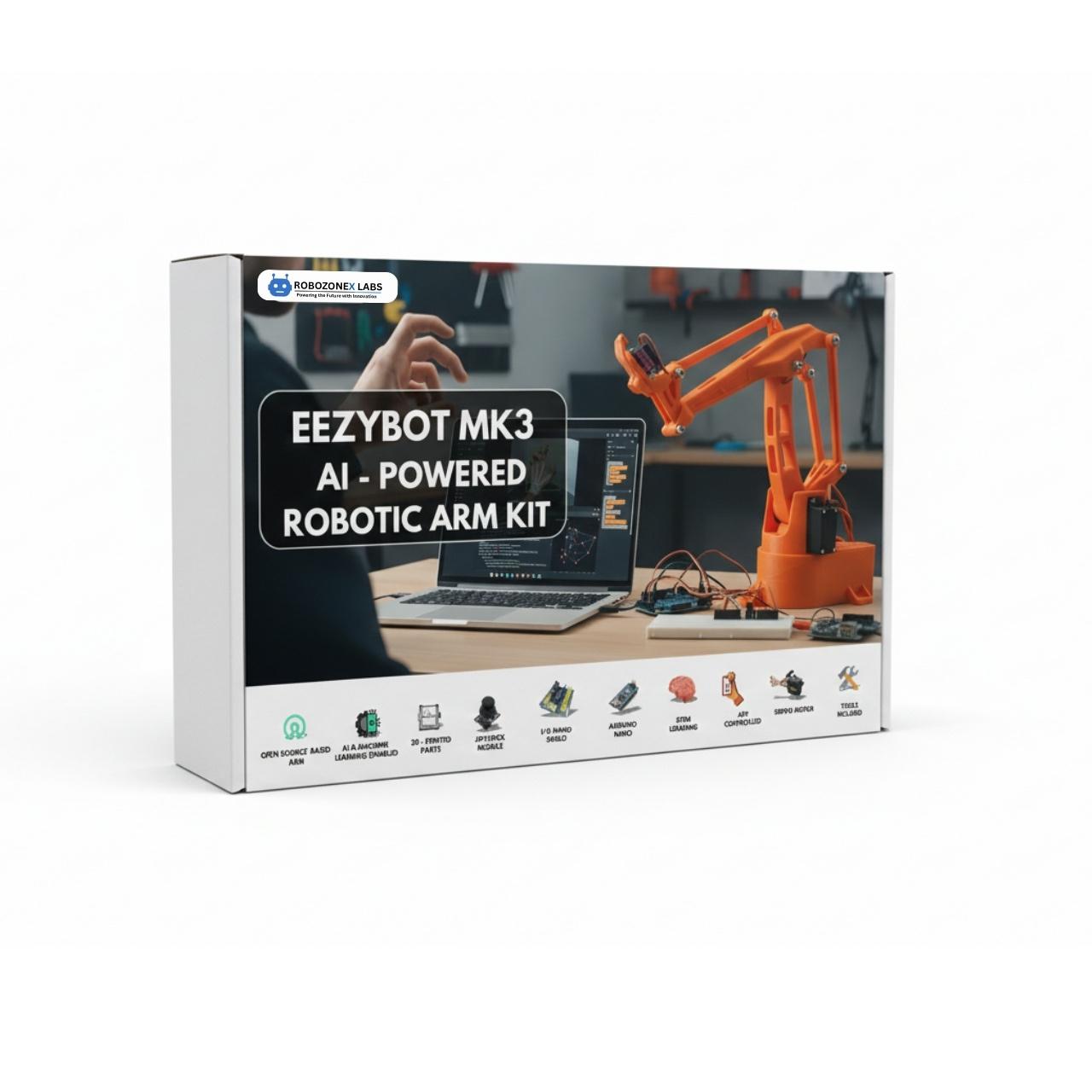
Forward vs. Inverse Kinematics: The Core Challenge In industrial robotics and automation, moving a robotic arm's end-effector (gripper) to a specific target point in space (X, Y, Z) is known as Inverse Kinematics (IK). - Forward Kinematics (FK): Given the servo joint angles (\theta1, \theta2, \theta3), calculate where the gripper is positioned (X, Y, Z). (Mathematically simple matrix multiplication). - Inverse Kinematics (IK): Given a desired physical object position (X, Y, Z), calculate the exact servo angles (\theta1, \theta2, \theta3) needed to reach it. (Requires trigonometric geometric solving or iterative Jacobian matrices). The RoboZoneX EEZYBOT-MK3 AI Robotic Arm Kit provides a rigid, 3D-printable parallel linkage design engineered specifically to make these equations intuitive to learn. --- Solving the Geometric 3-DOF Inverse Kinematics For a 3-axis articulated robotic arm with base rotation (\theta1), shoulder joint (\theta2), and elbow joint (\theta3): 1. Base Angle (Yaw) The base servo rotates around the vertical Z-axis to face the target coordinates (X, Y): $$\theta1 = \text{atan2}(Y, X)$$ 2. Planar Projection & Arm Reach Calculate the horizontal distanc...
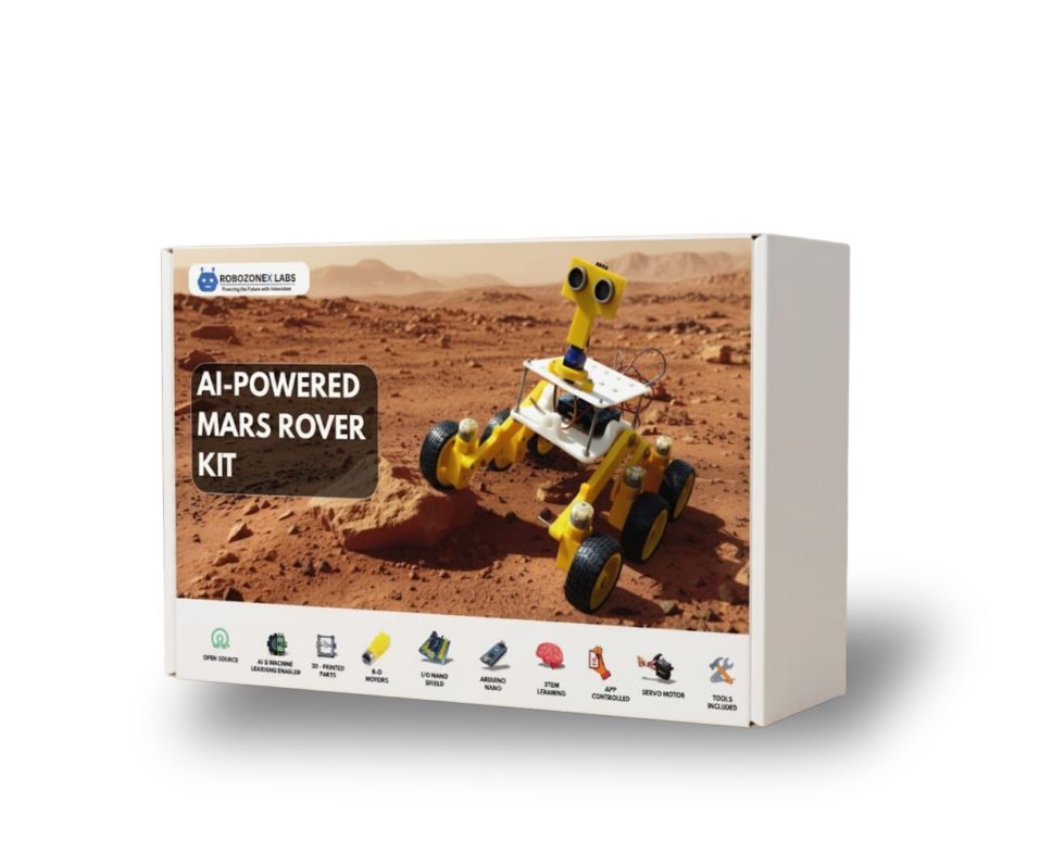
An in-depth mechanical and electronic breakdown of NASA-inspired Rocker-Bogie linkages, multi-wheel DC motor torque distribution, and integrating ESP32 telemetry for autonomous rough-terrain planetary rovers.

Introduction: The Mechanics of Open-Source Bipedal Locomotion Two-legged (bipedal) walking is one of the most challenging kinematics problems in educational robotics. Unlike wheeled mobile robots that maintain continuous static stability, bipedal companions like the RoboZoneX Otto Robot Kit rely on alternating dynamic center-of-mass balancing across two feet and four degrees of freedom (4-DOF). In this tutorial, we will break down the hardware architecture, servo zero-point calibration, walking gait mathematical models, and non-blocking sensor routines required to build an autonomous obstacle-avoiding bipedal robot from scratch. --- Hardware Architecture & Kinematic Chain The Otto bipedal platform utilizes four micro-servo actuators: 1. Left Leg Servo (Roll/Pitch Axis): Controls foot lift and lateral weight shifting. 2. Right Leg Servo (Roll/Pitch Axis): Coordinates weight transfer to the opposite foot. 3. Left Foot Servo (Yaw Axis): Drives forward/backward step strides. 4. Right Foot Servo (Yaw Axis): Completes the alternating stride cycle. Crucial Assembly Step: Servo Trimming & Center Pulse Before mounting the 3D-printed chassis horns, every servo must be electrically...